| |
||||||||

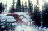
V. SLOPING ROOFS The design of sloped roofs in snowy regions has its own special set of problems. As with flat roofs, site orientation with respect to sun and storm winds can either exacerbate or mitigate roof snow accumulation. For example, a gable pitched roof with the ridge running east/west with a south storm wind will probably have the south facing portion of the sloped roof wind stripped of most of its snow cover and some of this blown onto the north portion of the roof. This drift surcharge load on the north side can become quite substantial. This north drift can easily build up over time as it is in shade from the southern sun, and solar melting will be minimal. Conversely, some mitigating drift effect will be achieved if the storm wind comes from the north. The north roof snow would be blown onto the south portion of the gable roof where more melting would occur. Alternately, a change in the ridge orientation here the ridge was in line with the storm winds would allow wind stripping to occur uniformly on each portion of the sloping gable roof in a manner somewhat similar to flat roofs. Drifting at projections and roof steps needs to also be considered as discussed above.Sloped roofs in snow country are best kept to very simple forms. Complex pitched shapes, dormers, valleys and multilevel steps all create a myriad of snow catchers and consequential unbalanced loading conditions and promote ice dams. Besides the loading problems, these shapes also create extremely difficult to solve flashing and waterproofing situations. Icing and ice dams can easily grow at these complex geometric intersections, further complicating the loading and waterproofing problems. Complex roof forms lead directly to roof leaks in snow country. A sloped roof in snow regions should always have at least one gable end where entering the building will not be hazardous due to snow or ice avalanching off the roof. Too many projects are de-signed with no consideration of where shedding roof snow will land. Many an automobile has been buried or severely damaged due to shedding snow and ice. People suffer the same fate with resulting severe injury or death. The designer must decide, "Do I keep the snow on the roof or do I let it shed off?" Roofing surfaces such as composition shingles and wood or concrete shakes tend to hold the snow on the roof. The granules and lapping layers of composition shingles allow the snow/ice to grip the sloping roof surface; similarly with shakes. The snow on these high coefficient of friction roofing materials tends to creep down toward the eave. If not restrained, the snow/ice will curl and eventually break loose and come crashing down. On the other hand, smooth metal roofing is very slippery with a melt water interface layer below the sloped roof snow. The snow will build up until the frictional resistance is overcome and then it will avalanche off almost instantly. Standing seams in metal roofs often freeze into snow blankets on the roof and then, when the snow slips, act as rails to accelerate the avalanche. (Figure 4) The ground impact zones for both the creep and sliding roof snow must be carefully allocated and designed to prevent damage or injury. Snow arresters (snow guards, fences) can be detailed to retain snow on the roof. Case Study Two, Mackinlay, Flood (1996) is an example of a steel bar as snow arrester at the eave. Concurrent with this arrester is an upslope, snow insulated and heat cable-traced gutter to intercept the melt water before it is exposed to freezing air, thus mitigating ice dam and icicle formation at the eave. The engineering for the loads imposed on snow arresters is explained by Tobiasson, Buska and Greatorex (1996). |
||
| |
||||||||
Roof Design in Regions of Snow and Cold
by Ian Mackinlay, FAIA; Richard S. Flood,
AIA/CSI and Anke Heidrich
Hjorth-Hansen, Holand, Løset & Norem (eds.) © 2000 Balkema,
Rotterdam. Proceedings of the Fourth International Conference on Snow Engineering,
Trondheim, Norway; 19-21 June 2000. Rotterdam: Balkema: 213-224. ISBN 90 5809
Photographs are by Ian Mackinlay except as noted.
 |
||||||
| Figure 4 | ||||||